In collaboration with Drs. Stuart Grant and David MacLeod in the Department of Anesthesiology in the Duke University Medical Center, we have been exploring the use of ARFI imaging to improve image guidance during regional anesthesia procedures.
B-mode imaging is used to help guide anesthetic injections during regional nerve blocks. B-mode imaging relies on acoustic impedance mismatches to scatter and reflect acoustic energy to generate images. Nerves can be difficult to visualize with B-mode imaging because they do not have appreciable ultrasonic contrast with adjacent soft tissues (i.e., muscle, fat, fascia). ARFI imaging utilizes acoustic radiation force to impulsively excite tissues with a modified diagnostic scanner, and the dynamic mechanical response of the tissue is monitored using conventional ultrasonic methods with the same transducer.
Nerve Imaging
We have performed ARFI imaging in situ on cadaveric sciatic nerves and in vivo in the brachial plexus and sciatic nerves. B-mode and ARFI images were acquired before, during and after saline injections. ECG image acquisition triggering was utilized in vivo to limit motion artifacts. ARFI images demonstrate that nerves are relatively stiffer than their adjacent tissue. Improved nerve contrast up to 600% has been observed in ARFI images when compared with B-mode images. Initial results of this work have been published in On the Feasibility of Imaging Peripheral Nerves Using Acoustic Radiation Force Impulse Imaging. Below are some representative images from that manuscript.

In vivo B-mode (left) and ARFI (right) images of the tibial and common peroneal nerves in a 29-year old subject, just distal to their bifurcation from the sciatic nerve in the popliteal fossa. The ARFI image was generated using two excitation focal zones at 15 and 20 mm with the VF10-5 linear array. The peak displacement in the ARFI image is 4 um. ECG data acquisition gating was not used in generating the ARFI image. Notice that the two nerves are clearly delineated as stiffer (darker) circular structures in cross-section; their location is not readily apparent in the B-mode image (they have been outlined in yellow (tibial) and green (popliteal) based on the ARFI image boundaries). The improvement in nerve contrast is over 600% in the ARFI image compared with the B-mode image.

In situ distal cadaveric sciatic nerve with an 18 gauge needle intentionally piercing the upper left quadrant of the nerve sheath, imaged using the VF10-5 linear array. There is significant decorrelation deep to the needle due to poor SNR but the tip of the needle and the edge of that decorrelation can be seen inside the left border of the sciatic nerve, which appears dark (stiff) in the ARFI image. The nerve contrast improvement is~300% in the ARFI image compared with the B-mode image.
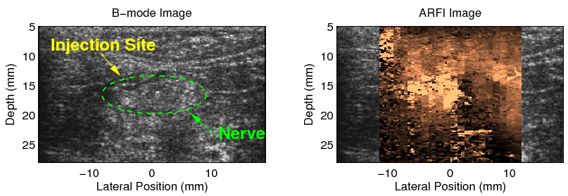
In situ cadaveric sciatic nerve after an intentional intraneural injection with 3 cc of saline in the left half of the nerve imaged using the VF10-5 linear array. The location of the nerve has been circled in the B-mode image using some circumferential landmarks from the corresponding ARFI image. The needle was removed before the image was acquired. Notice the ARFI image contrast reversal in the left half of the nerve that has been infused with saline compared with the right half of the nerve that was not injected.

Needle Imaging
ARFI imaging can also be used to enhance the visualization of needles; specifically the perturbations in the relative compliance of soft tissues adjacent to inserted needles. In B-mode imaging, needles appear brightly hyperechoic when properly aligned in the imaging plane at at small angels of insertion relative to the transducer face. However, when needles are slightly misaligned with the imaging plane or inserted at steeper angles, the majority of acoustic energy is reflected away from the transducer face, and the needle is not readily apparent in the B-mode image. In contrast, the soft tissue perturbations utilized by ARFI images are independent of the needle angle, and can tolerate slight imaging plane misalignment, allowing for improved needle visualization and a wider range of possible needle approaches for performing regional anesthesia procedures.

B-mode images of needles in degassed lean bovine muscle (top row) and with needle visualization algorithm applied (bottom row). Column 1 (Figures (a) and (d)) shows a 21G needle .75 mm elevationally off-axis from the transducer, column 2 (Figures (b) and (e)) shows a 25G needle 1.5 mm off-axis from the transducer, and column 3 (Figures (c) and (f)) shows an on-axis 18G needle at a 30-degree angle of insertion to the horizontal.
Injection Mapping
Details and images coming soon...
This work is supported by the Wallace H Coulter Foundation. For more information about this research, please contact Dr. Mark Palmeri (mark.palmeri@duke.edu).
Related Publications
Acoustic Radiation Force Impulse (ARFI) imaging-based needle visualization. Rotemberg, V, Palmeri M, Rosenzweig S, Grant S, Macleod D, Nightingale K. Ultrason Imaging. 2011 Jan;33(1):1-16.